【メモ】CatalystでのPBRとVRF

Catalyst3650, 3850等でPBRを使う時, VRFインタフェースとは併用できないので注意。

“互いに排他”とあります。

Cisco IOS XE Denali 16.1.1(Catalyst 3650 スイッチ) ソフトウェアコンフィギュレーションガイド

VRF と PBR は、スイッチ インターフェイス上で相互に排他的です。PBR がインターフェイスでイネーブルになっているときは、VRF をイネーブルにはできません。その反対の場合も同じで、VRF がインターフェイスでイネーブルになっているときは、PBR をイネーブルにできません。

VRFのsetコマンドも使えるものが限定的です。
set vrf や set global は利用できないようです。

また, デフォルトでプロセススイッチングになるのでFast Switchingを有効にするにはインタフェースで ip route cache policy を入れる必要があります。

EVE-NGのHTTPS化

公式のマニュアルまんまです。
自己証明書なので, ブラウザの警告がでるからアンチウィルスソフト使っている場合は適宜除外設定する。

公式マニュアル
http://www.eve-ng.net/documentation/howto-s/81-howto-enable-ssl-on-eve

SSL有効化

root@eve-ng:~# a2enmod ssl
Considering dependency setenvif for ssl:
Module setenvif already enabled
Considering dependency mime for ssl:
Module mime already enabled
Considering dependency socache_shmcb for ssl:
Enabling module socache_shmcb.
Enabling module ssl.
See /usr/share/doc/apache2/README.Debian.gz on how to configure SSL and create self-signed certificates.
To activate the new configuration, you need to run:
service apache2 restart

自己証明書作成

root@eve-ng:~#  openssl req -x509 -nodes -days 3650 -newkey rsa:2048 -keyout /etc/ssl/private/apache-selfsigned.key -out /etc/ssl/certs/apache-selfsigned.crt
Generating a 2048 bit RSA private key
..+++
.......................................+++
writing new private key to '/etc/ssl/private/apache-selfsigned.key'
-----
You are about to be asked to enter information that will be incorporated
into your certificate request.
What you are about to enter is what is called a Distinguished Name or a DN.
There are quite a few fields but you can leave some blank
For some fields there will be a default value,
If you enter '.', the field will be left blank.
-----
Country Name (2 letter code) [AU]:JP
State or Province Name (full name) [Some-State]:Tokyo
Locality Name (eg, city) []:
Organization Name (eg, company) [Internet Widgits Pty Ltd]:Personal
Organizational Unit Name (eg, section) []:
Common Name (e.g. server FQDN or YOUR name) []:192.168.10.20
Email Address []:

Conf修正

root@eve-ng:~# cat << EOF > /etc/apache2/sites-enabled/default-ssl.conf
<IfModule mod_ssl.c>
<VirtualHost _default_:443>
ServerAdmin webmaster@localhost
DocumentRoot /opt/unetlab/html/
ErrorLog /opt/unetlab/data/Logs/ssl-error.log
CustomLog /opt/unetlab/data/Logs/ssl-access.log combined
Alias /Exports /opt/unetlab/data/Exports
Alias /Logs /opt/unetlab/data/Logs
SSLEngine on
SSLCertificateFile /etc/ssl/certs/apache-selfsigned.crt
SSLCertificateKeyFile /etc/ssl/private/apache-selfsigned.key
<FilesMatch ".(cgi|shtml|phtml|php)$">
SSLOptions +StdEnvVars
</FilesMatch>
<Directory /usr/lib/cgi-bin>
SSLOptions +StdEnvVars
</Directory>
<Location /html5/>
Order allow,deny
Allow from all
ProxyPass http://127.0.0.1:8080/guacamole/ flushpackets=on
ProxyPassReverse http://127.0.0.1:8080/guacamole/
</Location>

<Location /html5/websocket-tunnel>
Order allow,deny
Allow from all
ProxyPass ws://127.0.0.1:8080/guacamole/websocket-tunnel
ProxyPassReverse ws://127.0.0.1:8080/guacamole/websocket-tunnel
</Location>
</VirtualHost>
</IfModule>
EOF

Apacheリスタート

root@eve-ng:~# /etc/init.d/apache2 restart
[ ok ] Restarting apache2 (via systemctl): apache2.service.

以上。簡単なのでやっておくべし。

HTTPSになっている

NetflowをElastiflowで取り込む

Elasticsearchで取り込んだデータをKibanaでインデックス化まではいけたのだけれど, ダッシュボードにNetflowがないのでフォーラムに問い合わせしてみたら, 「ElastiFlowをおすすめする」と言われたのでそちらでやってみた。

手順はここにある。
https://github.com/robcowart/elastiflow

しかし必要リソースが多い・・・。

flows/sec (v)CPUs Memory Disk (30-days) ES JVM Heap LS JVM Heap
250 4 24 GB 305 GB 8 GB 4 GB
1000 8 32 GB 1.22 TB 12 GB 4 GB
2500 12 64 GB 3.05 TB 24 GB 6 GB

手順

  1. 確認
  2. Javaのヒープサイズ確認
  3. Logstash Pluginインストール
  4. Git Hubから関連ファイル取得・配置
  5. 設定ファイル編集
  6. プロセス再起動
  7. Kibanaでインデックス作成・ダッシュボードjsonを読み込む

アップデート

もろもろアップデートしておく。なお, Elasticsearchのバージョンは6.2.4。

yum update -y

Javaのヒープサイズ変更

It is recommended that Logstash be given at least 2GB of JVM heap. If all options, incl. DNS lookups (requires version 3.0.10 or later of the DNS filter), are enabled increase this to 4GB. 

とあったので初期値1G, MAX値を4Gへ変更。

vi /etc/logstash/jvm.options
# Xms represents the initial size of total heap space
# Xmx represents the maximum size of total heap space

#-Xms256m
#-Xmx1g
-Xms1g
-Xmx4g

Logstash Pluginインストール

# ./logstash-plugin install logstash-codec-sflow
Validating logstash-codec-sflow
Installing logstash-codec-sflow
Installation successful
# ./logstash-plugin update logstash-codec-netflow
Updating logstash-codec-netflow
Updated logstash-codec-netflow 3.13.2 to 3.14.0
# ./logstash-plugin update logstash-input-udp
Updating logstash-input-udp
Updated logstash-input-udp 3.3.2 to 3.3.3
# ./logstash-plugin update logstash-filter-dns
Updating logstash-filter-dns
Updated logstash-filter-dns 3.0.9 to 3.0.10

Git Hubから関連ファイル取得・配置・編集

% git clone https://github.com/robcowart/elastiflow.git
% ls -l elastiflow
total 32
drwxrwxr-x. 2 centos centos 75 May 24 20:02 kibana
-rw-rw-r--. 1 centos centos 1026 May 24 20:02 LICENSE.md
drwxrwxr-x. 3 centos centos 23 May 24 20:02 logstash
drwxrwxr-x. 2 centos centos 54 May 24 22:49 logstash.service.d
drwxrwxr-x. 2 centos centos 26 May 24 20:02 profile.d
-rw-rw-r--. 1 centos centos 28091 May 24 20:02 README.md

設定ファイル配置

# cp -r ./elastiflow/logstash/elastiflow/ /etc/logstash/

設定ファイル編集。
netflow以外使わないので, それ以外のファイルはdisableにした。

10_input_ipfix_ipv4.logstash.conf.disabled
10_input_ipfix_ipv6.logstash.conf.disabled
10_input_netflow_ipv4.logstash.conf
10_input_netflow_ipv6.logstash.conf.disabled
10_input_sflow_ipv4.logstash.conf.disabled
10_input_sflow_ipv6.logstash.conf.disabled
20_filter_10_begin.logstash.conf
20_filter_20_netflow.logstash.conf
20_filter_30_ipfix.logstash.conf.disabled
20_filter_40_sflow.logstash.conf.disabled
20_filter_90_post_process.logstash.conf
30_output.logstash.conf

インプットファイル編集

# vi 10_input_netflow_ipv4.logstash.conf

変更点。

host => "${ELASTIFLOW_NETFLOW_IPV4_HOST:172.16.10.50}"
port => "${ELASTIFLOW_NETFLOW_IPV4_PORT:9995}"

アウトプットファイル編集

# vi 30_output.logstash.conf

変更点。

hosts => [ "${ELASTIFLOW_ES_HOST:172.16.10.50:9200}" ]
user => "${ELASTIFLOW_ES_USER:elastic}"
password => "${ELASTIFLOW_ES_PASSWD:elastic}"

起動スクリプト配置

# cp -r ./elastiflow/logstash.service.d/ /etc/systemd/system/

起動スクリプト編集

# vi /etc/systemd/system/logstash.service.d/elastiflow.conf

変えたところは以下。

Environment="ELASTIFLOW_NAMESERVER=1.1.1.1"
Environment="ELASTIFLOW_ES_HOST=172.16.10.50"
Environment="ELASTIFLOW_ES_PASSWD=changeme"
Environment="ELASTIFLOW_NETFLOW_IPV4_HOST=172.16.10.50"
Environment="ELASTIFLOW_NETFLOW_IPV4_PORT=9995"

アプリケーションID登録。

# vi /etc/logstash/elastiflow/dictionaries/app_id.srctype.yml

Cisco841を登録。

"192.168.1.2": "c841m"

pipeline.ymlに以下追加。合わせてnetflowの行はコメントアウト。

# For ElastiFlow
- pipeline.id: elastiflow
path.config: "/etc/logstash/elastiflow/conf.d/*.conf"

プロセス再起動

#systemctl restart logstash
#systemctl daemon-reload

Kibanaにjson取り込み

「Management -> Save Objects -> Import」でGitから取得したelastiflow.dashboards.jsonをインポート。

できた!

ただ, うちの仮想マシンのスペック不足で結構な頻度でエラーが出る。
この辺は今の状況ではどうしようもないなー。

【メモ】MTUの種類

Catalystでジャンボフレームに対応させる設定を調べていて, MTU周りについてのメモ。

参考)
インターフェイスおよびハードウェア コンポーネント コンフィギュレーション ガイド、Cisco IOS XE Release 3SE(Catalyst 3650 スイッチ)
Interface and Hardware Component Configuration Guide, Cisco IOS XE Release 3SE (Catalyst 3650 Switches)
微妙に日本語と英語のサイトが違う。

System MTU Values

The following MTU values can be configured:
  • System MTU–This value applies to switched packets on the Gigabit Ethernet and 10-Gigabit Ethernet ports of the switch. Use the system mtu bytes global configuration command to specify the system jumbo MTU value.
  • System Jumbo MTU–This value applies to switched packets on the Gigabit Ethernet and 10-Gigabit Ethernet ports of the switch. Use the system mtu jumbo bytesglobal configuration command to specify the system jumbo MTU value.
  • Protocol-specific MTU–This value applies only to routed packets on all routed ports of the switch or switch stack. Use the ip mtu bytes or ipv6 mtu bytes interface configuration command to specify the protocol-specific MTU value.

・system mtu コマンド
1Gと10Gのスイッチングポートに適用。設定後再起動が必要。
・system mtu jumbo コマンド
1Gと10Gのスイッチングポートに適用。設定後再起動が必要。
上と何が違うんだ???
・ip mtu コマンド
Routed-portに適用される設定。インタフェースに設定。再起動不要。
system mtu の値より大きいものは設定不可。

うーん。「system mtu」と「system mtu jumbo」違いが分からない。
と, ここでCat3650が1Gbps以上のインタフェースしか持っていないからこういうマニュアルになっているのか?と思って別の機種も含めて調べてみると・・・。

 Catalyst スイッチでのジャンボ/ジャイアント フレーム サポートの設定例

すべての 10/100 インターフェイスで MTU を変更するには、system mtu コマンドを使用します。 このコマンドは、10/100 インターフェイスについてのみ効力があります。
3750(config)# system mtu 15463750(config)# exit3750# reload
すべてのギガビット イーサネット インターフェイスで MTU を変更するには、system mtu jumbo コマンドを使用します。 このコマンドは、ギガビット イーサネット インターフェイスについてのみ効力があります。
3750(config)# system mtu jumbo 90003750(config)# exit3750# reload
: system mtu コマンドはギガビット イーサネット ポートには影響せず、 system mtu jumbo コマンドは 10/100 ポートには影響しません。 system mtu jumbo コマンドを設定していない場合は、system mtu コマンドの設定がすべてのギガビット イーサネット インターフェイスに適用されます。

とあった。1G以上のインタフェースしかないスイッチでは「system mtu」でも「system mtu jumbo」でもどちらでもすればよさそう。

【メモ】elasticsearchアップグレードしたらエラーで起動しない件

Just a note。

こんなメッセージが出て起動しなかった。

java.lang.IllegalArgumentException: plugin [ingest-geoip] is incompatible with version [6.2.4]; was designed for version [6.1.2]
at org.elasticsearch.plugins.PluginInfo.readFromProperties(PluginInfo.java:237) ~[elasticsearch-6.2.4.jar:6.2.4]
at org.elasticsearch.plugins.PluginInfo.readFromProperties(PluginInfo.java:184) ~[elasticsearch-6.2.4.jar:6.2.4]
at org.elasticsearch.bootstrap.Spawner.spawnNativePluginControllers(Spawner.java:75) ~[elasticsearch-6.2.4.jar:6.2.4]
at org.elasticsearch.bootstrap.Bootstrap.setup(Bootstrap.java:167) ~[elasticsearch-6.2.4.jar:6.2.4]
at org.elasticsearch.bootstrap.Bootstrap.init(Bootstrap.java:323) [elasticsearch-6.2.4.jar:6.2.4]
at org.elasticsearch.bootstrap.Elasticsearch.init(Elasticsearch.java:121) [elasticsearch-6.2.4.jar:6.2.4]
at org.elasticsearch.bootstrap.Elasticsearch.execute(Elasticsearch.java:112) [elasticsearch-6.2.4.jar:6.2.4]
at org.elasticsearch.cli.EnvironmentAwareCommand.execute(EnvironmentAwareCommand.java:86) [elasticsearch-6.2.4.jar:6.2.4]
at org.elasticsearch.cli.Command.mainWithoutErrorHandling(Command.java:124) [elasticsearch-cli-6.2.4.jar:6.2.4]
at org.elasticsearch.cli.Command.main(Command.java:90) [elasticsearch-cli-6.2.4.jar:6.2.4]
at org.elasticsearch.bootstrap.Elasticsearch.main(Elasticsearch.java:92) [elasticsearch-6.2.4.jar:6.2.4]
at org.elasticsearch.bootstrap.Elasticsearch.main(Elasticsearch.java:85) [elasticsearch-6.2.4.jar:6.2.4]

一度6.1.3へダウングレードして, ingest-geoipを削除。 その後またアップグレードで復旧。

NAT on a stick

例えばNATに対応していない機器(L3SW等)があったとして, それでもNATしなくてはならない場合。
図のようにワンアームでルータをつないでNATボックスとする構成が取れる。

図ではルータのアイコンになっているけれど, R1がNATに対応していないとき

ヘアピンNATやNAT on a Stick と呼ぶらしい。
Ciscoサイトを参照して検証する。
参照URL:スティック上のネットワーク アドレス変換

構成概要

    • 172.16.10.0/24 を172.20.10.0/24 へネットワークNATする。
    • NATポイントはR2。
    • VPC2は172.20.10.0/24のアドレスでアクセスする。

      そのため, R1では必然的にPBRを利用してVPC1の通信をR2へ転送する。

      Config

      ※ 抜粋
      R1 Config

      !
      interface Ethernet0/0
      description to R3
      ip address 192.168.2.1 255.255.255.0
      !
      interface Ethernet0/1
      description to R2
      ip address 10.10.10.1 255.255.255.0
      !
      interface Ethernet0/2
      description to R4
      ip address 192.168.1.1 255.255.255.0
      ip policy route-map PBR
      !
      ip route 172.16.10.0 255.255.255.0 192.168.1.2
      ip route 172.16.20.0 255.255.255.0 192.168.2.2
      ip route 172.20.10.0 255.255.255.0 10.10.10.2
      !
      ip access-list extended PBR
      permit ip 172.16.10.0 0.0.0.255 any
      !
      !
      route-map PBR permit 10
      match ip address PBR
      set ip next-hop 10.10.10.2
      !
      !

      R2 Config

      !
      interface Loopback0
      ip address 1.1.1.1 255.255.255.255
      ip nat outside
      ip virtual-reassembly in
      !
      interface Ethernet0/0
      description to R1
      ip address 10.10.10.2 255.255.255.0
      ip nat inside
      ip virtual-reassembly in
      ip policy route-map NAT
      !
      !
      ip nat inside source static network 172.16.10.0 172.20.10.0 /24 no-alias
      ip route 0.0.0.0 0.0.0.0 10.10.10.1
      ip route 172.20.10.0 255.255.255.0 Ethernet0/0
      !
      ip access-list extended PBR
      permit ip 172.16.10.0 0.0.0.255 any
      permit ip any 172.20.10.0 0.0.0.255
      !
      !
      route-map NAT permit 10
      match ip address PBR
      set interface Loopback0
      !

      パケットフロー
      CiscoルータにおけるNATの処理は公式ページにあるとおり。
      参考:NATの処理順序
      今回関係する箇所を太文字で。

      1. IPSec ACL チェック
      2. 復号化
      3. 入力ACLチェック
      4. 入力レート制限をチェック
      5. 入力アカウンティング
      6. Web キャッシュにリダイレクト
      7. ポリシー ルーティング
      8. ルーティング
      9. Inside から Outside への NAT
      10. クリプト(暗号化用のマップのチェックとマーク)
      11. 出力アクセス リストをチェック
      12. CBAC検査
      13. TCP インターセプト
      14. 暗号化
      15. キューイング
      1. IPSec ACL チェック
      2. 復号化
      3. 入力ACLチェック
      4. 入力レート制限をチェック
      5. 入力アカウンティング
      6. Web キャッシュにリダイレクト
      7. OutsideからInsideへの NAT
      8. ポリシー ルーティング
      9. ルーティング
      10. クリプト(暗号化用のマップのチェックとマーク)
      11. 出力アクセス リストをチェック
      12. CBAC 検査
      13. TCP インターセプト
      14. 暗号化
      15. キューイング

      プチ解説

      @R1
      NAT変換後のアドレスをR2へ向けます。

      ip route 172.16.20.0 255.255.255.0 192.168.2.2

      VPC1からのトラフィックをR2(NATボックス)へ捻じ曲げます。

      interface Ethernet0/2
      description to R4
      ip address 192.168.1.1 255.255.255.0
      ip policy route-map PBR
      !
      !
      ip access-list extended PBR
      permit ip 172.16.10.0 0.0.0.255 any
      !
      !
      route-map PBR permit 10
      match ip address PBR
      set ip next-hop 10.10.10.2

      @R2
      物理IFをinsideに指定します。

      interface Ethernet0/0
      description to R1
      ip address 10.10.10.2 255.255.255.0
      ip nat inside
      ip virtual-reassembly in

      Loopbackをoutsideに指定します。

      interface Loopback0
      ip address 1.1.1.1 255.255.255.255
      ip nat outside
      ip virtual-reassembly in

      NAT設定。IOS15以降はno-aliasが必要です。

      ip nat inside source static network 172.16.10.0 172.20.10.0 /24 no-alias

      global insideのアドレスを自身に持たせるためStatic Routeを物理IFへ指定します。
      が, この構成ではなくてもいけました。(NATの処理フロー見ると不要な気がするんですが未だ理解できず。)

      ip route 172.20.10.0 255.255.255.0 Ethernet0/0

      NAT対象となる通信をPBRでLoopbackインタフェース(outside IF)へ送り込みます。これでinside-outsideに偽装します。

      interface Ethernet0/0
      description to R1
      ip address 10.10.10.2 255.255.255.0
      ip nat inside
      no ip virtual-reassembly in
      ip policy route-map NAT
      !
      !
      ip access-list extended PBR
      permit ip 172.16.10.0 0.0.0.255 any
      permit ip any 172.20.10.0 0.0.0.255
      !
      !
      route-map NAT permit 10
      match ip address PBR
      set interface Loopback0
      !

      通信確認。

      VPCS> ping 172.16.20.1

      84 bytes from 172.16.20.1 icmp_seq=1 ttl=251 time=1.802 ms
      84 bytes from 172.16.20.1 icmp_seq=2 ttl=251 time=3.606 ms
      84 bytes from 172.16.20.1 icmp_seq=3 ttl=251 time=4.168 ms
      84 bytes from 172.16.20.1 icmp_seq=4 ttl=251 time=3.517 ms
      84 bytes from 172.16.20.1 icmp_seq=5 ttl=251 time=3.150 ms


      R2#sh ip nat translations
      Pro Inside global Inside local Outside local Outside global
      icmp 172.20.10.10:28052 172.16.10.10:28052 172.16.20.1:28052 172.16.20.1:28052
      icmp 172.20.10.10:28308 172.16.10.10:28308 172.16.20.1:28308 172.16.20.1:28308
      icmp 172.20.10.10:28564 172.16.10.10:28564 172.16.20.1:28564 172.16.20.1:28564
      icmp 172.20.10.10:28820 172.16.10.10:28820 172.16.20.1:28820 172.16.20.1:28820
      icmp 172.20.10.10:29076 172.16.10.10:29076 172.16.20.1:29076 172.16.20.1:29076
      --- 172.20.10.10 172.16.10.10 --- ---
      --- 172.20.10.0 172.16.10.0 --- ---
      R2#

      VPCS> ping 172.20.10.10

      84 bytes from 172.20.10.10 icmp_seq=1 ttl=59 time=2.539 ms
      84 bytes from 172.20.10.10 icmp_seq=2 ttl=59 time=4.796 ms
      84 bytes from 172.20.10.10 icmp_seq=3 ttl=59 time=5.276 ms
      84 bytes from 172.20.10.10 icmp_seq=4 ttl=59 time=4.397 ms
      84 bytes from 172.20.10.10 icmp_seq=5 ttl=59 time=6.855 ms

      VPCS>

      注意点

      Loopback IFへトラフィックを投げるのでCPU処理に落ちます。
      スループットが気になる場合は物理的に(もしくはトランク等して)2本インタフェースを用意したほうがベター。
      IOS12台と15台でコマンドが若干違うので古いバージョンを使うときは確認しましょう。

      EVE-NGインストールメモ

      GNS3の代わりになるシミュレータ。
      VMWare Workstation上で動かせるので入れてみた。

      事前準備

      – Win10 + VMWare Workstation にOVAファイルを展開して利用する。
      ここからコミュニティ版をダウンロード。
      http://www.eve-ng.net/index.php/community
      – Windowsのクライアントパックもダウンロード&インストール。
      http://www.eve-ng.net/downloads/windows-client-side-pack

      – 仮想マシンをインポート。
      プロセッサのIntel VT-xにチェックを入れる。

      – 起動。ログイン。
      root/eve

      – ログインするとパスワード変えろと言われる。

      – 続いてhostname。そのまま。

      – ドメイン。そのまま。

       – IPアドレスどうするかと。変わると面倒なのでStatic。

      – 適当に。

      – サブネットマスク入れる。

      – ゲートウェイ設定。VMWare Playerは「1」ではなく「2」がゲートウェイになるそうな。

      – DNSも同じにして。この後セカンダリも入れるので今流行りの「1.1.1.1」にした。

      – NTP無し。

      – Proxy無し。

      – で完了&再起動。

      – 改めてログインする。

      – いけてる。

      – ブラウザでアクセス。
      admin/eve

      – GNS3ではプロジェクトだったけれど, EVE-NGではラボ(Lab)だそうな。

      その後。

      – sshでログイン。
      – IOS/IOUをアップロード。ライセンス設定。
        IOSはbinからimageへファイル変更。permission変更。IDLE-PC設定。
      http://www.eve-ng.net/documentation/howto-s/64-howto-add-dynamips-images-cisco-ios

      – パーミッション変更

      # /opt/unetlab/wrappers/unl_wrapper -a fixpermissions

      個人的な感想ですが, 慣れればGNS3よりもこっちのほうが良いかもしれない。なんとなく安定しているし。
      しかし, ホストPCのVMWare Playerの上で動かす場合, リモートからアクセスできないので, 例えばUbuntu上でサービスとして動かすGNS3のようにX Forwardingできる方が検証環境としては場所にとらわれなくてよいかなとも思った。

      enable secretにしよう

      Cisco公式サイトでは「enable passwordは使用しないでください」とお達しが出ています。
      参考) Cisco IOS のパスワード暗号化情報

      enable secret はMD5ベースで不可逆なので, まぁ良いでしょう。
      service-password encryption はsimple Vigen re cipher(なんだこれ)を使っているからショルダーハック防止程度にしかならないと。

      password 7 で設定されているものは復元可能なのでやめましょうね。
      というお話。

      実際に復号化できたので衝撃的でした。

      cisco#enable algorithm-type ?
      md5 Encode the password using the MD5 algorithm
      scrypt Encode the password using the SCRYPT hashing algorithm
      sha256 Encode the password using the PBKDF2 hashing algorithm

      MD5からも変更できるのね。今ならsha256かな。

      [OSPF] DRとBDRの話

      最近になってOSPFでDRに関する認識が間違えていたことに気がついた。

      ということでメモ。
      何かというと, DRが落ちるとBDRがDRに昇格されるまでの間, そのネットワーク内ではルートが消失するということ。
      正直, BDRがDB保持しているのでネイバーはそれを即時引き継ぐものだと思っていた。
      しかし, とある環境で「なーんかメインの経路じゃないルータが落ちてPingロストするなー」なんて思って調べていて, わかったのがこれ。◯十年ネットワークエンジニアやっていたけど, この挙動は全く知なかったし意識したこともなかった。「障害ポイントによっては収束に時間がかかる場合があるよな」くらいの認識でした。
      まだまだ知らないことばかり。
      OSPF v2のRFC「https://www.ietf.org/rfc/rfc2328.txt」にも書いてありました。
      Section 2 of this document discusses the directed graph
      representation of an area. Router nodes are labelled with their
      Router ID. Transit network nodes are actually labelled with the
      IP address of their Designated Router. It follows that when the
      Designated Router changes, it appears as if the network node on
      the graph is replaced by an entirely new node. This will cause
      the network and all its attached routers to originate new LSAs.
      Until the link-state databases again converge, some temporary
      loss of connectivity may result.
      This may result in ICMP
      unreachable messages being sent in response to data traffic.
      For that reason, the Designated Router should change only
      infrequently. Router Priorities should be configured so that
      the most dependable router on a network eventually becomes
      Designated Router.

      改めて検証してみる。
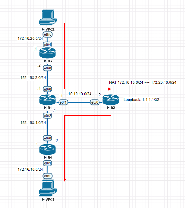
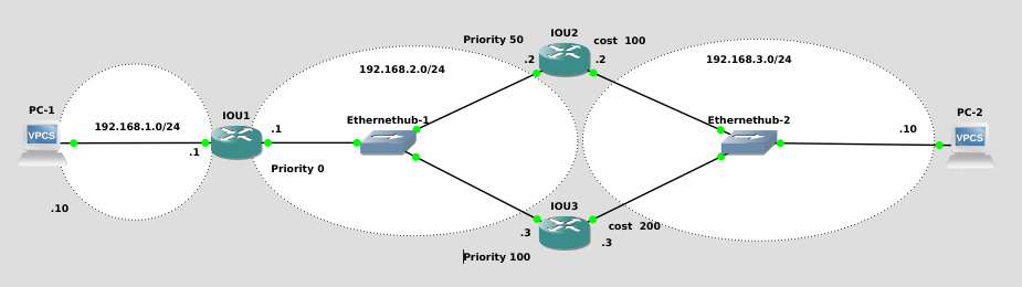
      ルータ3台でOSPFを組むシンプルな構成。
      PC1からPC2の経路はRouter1~Router2となるようにOSPFのコストを調整する。その上で, Router 1のPriorityを0にしてDR選出から外し, 2のPriorityを50, 3のPriorityを100にする。これで, 通信経路はRouter2をメインとするが, DRはRouter3になる。

      正常時のshow ip ospf neとshow ip ro の出力結果。設定どおり。

      Router1のネイバー

      IOU1#sh ip ospf ne

      Neighbor ID Pri State Dead Time Address Interface
      192.168.3.2 50 FULL/BDR 00:00:35 192.168.2.2 Ethernet0/0
      192.168.3.3 100 FULL/DR 00:00:31 192.168.2.3 Ethernet0/0

      IOU1#sh ip route
      Codes: L - local, C - connected, S - static, R - RIP, M - mobile, B - BGP
      D - EIGRP, EX - EIGRP external, O - OSPF, IA - OSPF inter area
      N1 - OSPF NSSA external type 1, N2 - OSPF NSSA external type 2
      E1 - OSPF external type 1, E2 - OSPF external type 2
      i - IS-IS, su - IS-IS summary, L1 - IS-IS level-1, L2 - IS-IS level-2
      ia - IS-IS inter area, * - candidate default, U - per-user static route
      o - ODR, P - periodic downloaded static route, H - NHRP, l - LISP
      + - replicated route, % - next hop override

      Gateway of last resort is not set

      192.168.1.0/24 is variably subnetted, 2 subnets, 2 masks
      C 192.168.1.0/24 is directly connected, Ethernet0/1
      L 192.168.1.1/32 is directly connected, Ethernet0/1
      192.168.2.0/24 is variably subnetted, 2 subnets, 2 masks
      C 192.168.2.0/24 is directly connected, Ethernet0/0
      L 192.168.2.1/32 is directly connected, Ethernet0/0
      O 192.168.3.0/24 [110/110] via 192.168.2.2, 00:10:35, Ethernet0/0

      Router 2のネイバー

      IOU2#sh ip ospf ne
      Neighbor ID Pri State Dead Time Address Interface
      192.168.2.1 0 FULL/DROTHER 00:00:33 192.168.2.1 Ethernet0/0
      192.168.3.3 100 FULL/DR 00:00:35 192.168.2.3 Ethernet0/0
      IOU2#sh ip route 
      Codes: L - local, C - connected, S - static, R - RIP, M - mobile, B - BGP
      D - EIGRP, EX - EIGRP external, O - OSPF, IA - OSPF inter area
      N1 - OSPF NSSA external type 1, N2 - OSPF NSSA external type 2
      E1 - OSPF external type 1, E2 - OSPF external type 2
      i - IS-IS, su - IS-IS summary, L1 - IS-IS level-1, L2 - IS-IS level-2
      ia - IS-IS inter area, * - candidate default, U - per-user static route
      o - ODR, P - periodic downloaded static route, H - NHRP, l - LISP
      + - replicated route, % - next hop override

      Gateway of last resort is not set

      O 192.168.1.0/24 [110/110] via 192.168.2.1, 00:11:53, Ethernet0/0
      192.168.2.0/24 is variably subnetted, 2 subnets, 2 masks
      C 192.168.2.0/24 is directly connected, Ethernet0/0
      L 192.168.2.2/32 is directly connected, Ethernet0/0
      192.168.3.0/24 is variably subnetted, 2 subnets, 2 masks
      C 192.168.3.0/24 is directly connected, Ethernet0/1
      L 192.168.3.2/32 is directly connected, Ethernet0/1

      Router 3のネイバー

      IOU3#sh ip ospf
      *Apr 18 07:04:07.804: %SYS-5-CONFIG_I: Configured from console by console
      IOU3#sh ip ospf ne

      Neighbor ID Pri State Dead Time Address Interface
      192.168.2.1 0 FULL/DROTHER 00:00:38 192.168.2.1 Ethernet0/0
      192.168.3.2 50 FULL/BDR 00:00:34 192.168.2.2 Ethernet0/0
      IOU3#sh ip route 
      Codes: L - local, C - connected, S - static, R - RIP, M - mobile, B - BGP
      D - EIGRP, EX - EIGRP external, O - OSPF, IA - OSPF inter area
      N1 - OSPF NSSA external type 1, N2 - OSPF NSSA external type 2
      E1 - OSPF external type 1, E2 - OSPF external type 2
      i - IS-IS, su - IS-IS summary, L1 - IS-IS level-1, L2 - IS-IS level-2
      ia - IS-IS inter area, * - candidate default, U - per-user static route
      o - ODR, P - periodic downloaded static route, H - NHRP, l - LISP
      + - replicated route, % - next hop override

      Gateway of last resort is not set

      O 192.168.1.0/24 [110/210] via 192.168.2.1, 00:12:06, Ethernet0/0
      192.168.2.0/24 is variably subnetted, 2 subnets, 2 masks
      C 192.168.2.0/24 is directly connected, Ethernet0/0
      L 192.168.2.3/32 is directly connected, Ethernet0/0
      192.168.3.0/24 is variably subnetted, 2 subnets, 2 masks
      C 192.168.3.0/24 is directly connected, Ethernet0/1
      L 192.168.3.3/32 is directly connected, Ethernet0/1

      と, ここまでやってCiscoでは収束が早くて事象が出ない。 たまにPingロスト起きるけどこれOSPF関係ないやつだ。

      Debugとってみたらコンマ数秒で切り替わっていたのでCiscoはよく出来ているということがわかりました。
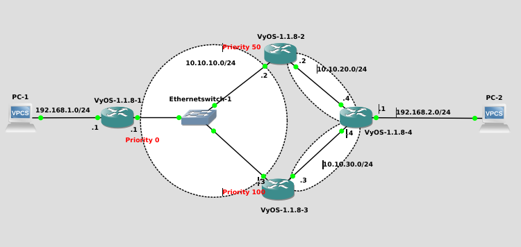

      ということでVyOSで検証。

      VyOSではBDRがいなくなるとルートアップデートしないというバグらしき挙動をするので構成はちょっと変えた。

      VyOS1のステータス。VyOS3がDRでVyOS2がBDR。PC2への宛先はVyOS2に向いている。なお, Helloは5秒。Deadは15秒にした。

      vyos1@vyos:~$ sh ip ospf ne

      Neighbor ID Pri State Dead Time Address Interface RXmtL RqstL DBsmL
      10.10.20.2 50 Full/Backup 11.994s 10.10.10.2 eth0:10.10.10.1 0 0 0
      10.10.10.3 100 Full/DR 10.991s 10.10.10.3 eth0:10.10.10.1 0 0 0
      vyos@vyos:~$ sh ip route
      Codes: K - kernel route, C - connected, S - static, R - RIP, O - OSPF,
      I - ISIS, B - BGP, > - selected route, * - FIB route

      O 10.10.10.0/24 [110/10] is directly connected, eth0, 00:17:16
      C>* 10.10.10.0/24 is directly connected, eth0
      O>* 10.10.20.0/24 [110/30] via 10.10.10.2, eth0, 00:00:08
      O>* 10.10.30.0/24 [110/40] via 10.10.10.2, eth0, 00:00:08
      C>* 127.0.0.0/8 is directly connected, lo
      O 192.168.1.0/24 [110/10] is directly connected, eth3, 00:17:16
      C>* 192.168.1.0/24 is directly connected, eth3
      O>* 192.168.2.0/24 [110/40] via 10.10.10.2, eth0, 00:00:08

      この時点で, PC1からPC2への経路はVyOS1~VyOS2~VyOS4となっている。VyOS3はバックアップラインとなっている。
      ここで, 通信に影響の無いはずのVyOS3(DR)のインタフェースをDisableにする。
      VyOS3

      vyos3@vyos# set interfaces ethernet eth0 disable
      [edit]
      vyos@vyos# commit
      [edit]
      vyos@vyos#

      VyOS1

      vyos1@vyos:~$ sh ip ro
      Codes: K - kernel route, C - connected, S - static, R - RIP, O - OSPF,
      I - ISIS, B - BGP, > - selected route, * - FIB route

      C>* 10.10.10.0/24 is directly connected, eth0
      C>* 127.0.0.0/8 is directly connected, lo
      O 192.168.1.0/24 [110/10] is directly connected, eth3, 00:33:43
      C>* 192.168.1.0/24 is directly connected, eth3
      vyos@vyos:~$
      vyos@vyos:~$ sh ip ospf ne

      Neighbor ID Pri State Dead Time Address Interface RXmtL RqstL DBsmL
      10.10.20.2 50 Full/DR 14.753s 10.10.10.2 eth0:10.10.10.1 1 0 0

      Pingの状態はというと・・・。

      84 bytes from 192.168.2.10 icmp_seq=136 ttl=61 time=4.304 ms
      84 bytes from 192.168.2.10 icmp_seq=137 ttl=61 time=5.105 ms
      *192.168.1.1 icmp_seq=138 ttl=64 time=0.999 ms (ICMP type:3, code:0, Destination network unreachable)
      *192.168.1.1 icmp_seq=139 ttl=64 time=0.832 ms (ICMP type:3, code:0, Destination network unreachable)
      *192.168.1.1 icmp_seq=140 ttl=64 time=0.925 ms (ICMP type:3, code:0, Destination network unreachable)
      *192.168.1.1 icmp_seq=141 ttl=64 time=1.416 ms (ICMP type:3, code:0, Destination network unreachable)
      192.168.2.10 icmp_seq=142 timeout
      *192.168.1.1 icmp_seq=143 ttl=64 time=1.184 ms (ICMP type:3, code:0, Destination network unreachable)
      192.168.2.10 icmp_seq=144 timeout
      *192.168.1.1 icmp_seq=145 ttl=64 time=1.185 ms (ICMP type:3, code:0, Destination network unreachable)
      192.168.2.10 icmp_seq=146 timeout
      *192.168.1.1 icmp_seq=147 ttl=64 time=1.224 ms (ICMP type:3, code:0, Destination network unreachable)
      192.168.2.10 icmp_seq=148 timeout
      *192.168.1.1 icmp_seq=149 ttl=64 time=0.886 ms (ICMP type:3, code:0, Destination network unreachable)
      192.168.2.10 icmp_seq=150 timeout
      192.168.2.10 icmp_seq=151 timeout
      192.168.2.10 icmp_seq=152 timeout
      84 bytes from 192.168.2.10 icmp_seq=153 ttl=61 time=3.531 ms

      16秒ほどパケロスしていた。
      VyOSなので, DRが切り替わってBDRが選出されるまでの間が通信断になっていると思われる。

      OSPFの仕様ということでしょうがないのかもしれないが, アクティブなルートに関係ないところでDRが落ちると影響出るというのは設計時には要注意ですね。
      アップデートの負荷が小さいのであれば, イーサネットでもPoint-to-Multipointにした方が良いのではないかと思いました。

      ubuntu 17.10 にGNS3を入れる

      環境はWin10 + VMWare Workstation + Ubuntu 17.10 server

      SSHDインストール

      # apt-get install openssh-server -y

      ※ sshdの設定 ※ 適宜Password認証許可等

      GNS3インストール

      参考
      # apt install software-properties-common
      # add-apt-repository ppa:gns3/ppa
      # apt-get update
      # apt-get install gns3-gui
      # dpkg --add-architecture i386
      # apt-get update
      # apt-get install gns3-iou

      ※ GNS3を利用するユーザにkvmのグループ追加
      これをしないとqemuのアプライアンスが利用できない。(kvmの権限がないためエラーとなる)

      # usermod -a -G kvm ubuntu

      その他設定

      ・コンソールをEtermに変更

      # apt-get install eterm

      カスタムコンソールで

      Eterm -e /bin/sh -c "telnet 127.0.0.1 5009"

      とする。

      ・ASAはHDDのタイプをVirtioにする

      ・Cisco IOUはライセンス登録しないと利用できない