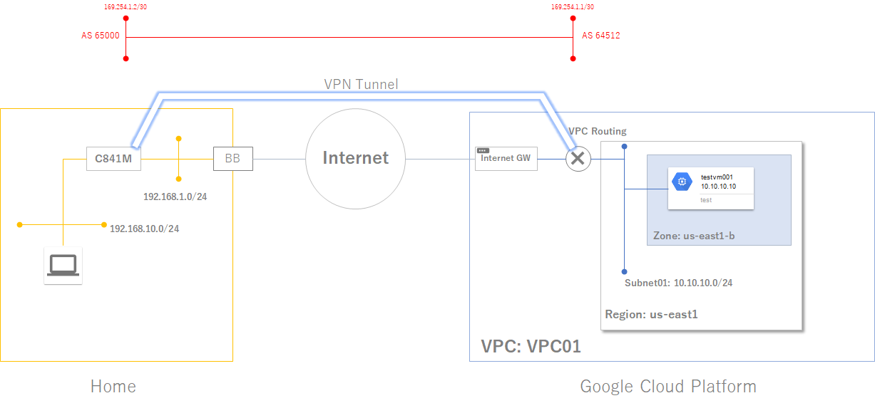
GCPとのVPN接続で, ポリシーベースではなくルーティングベースでやってみる。
構成は前回とほぼ変わらず。
クラウドルータとの間のセグメントが増えた感じ。
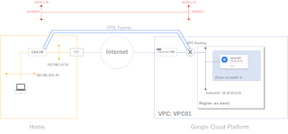 |
| GCP側にBGPルータができ, それとのルーティング設定が追加となる |
前提条件(ポリシーベースの前提を大体引き継ぐ)
- GCPのアカウント設定済み
- (VPC作成済み, VPC作成後のインスタンスも作成済み)
- 家側のNAT設定済み
- ルーティングベースなので, VTIを採用
流れ
1. クラウドルータ設定
2. VPN設定(Cisco)
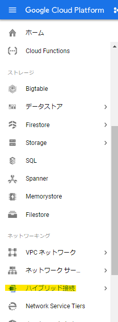
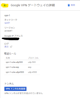
1. クラウドルータ設定
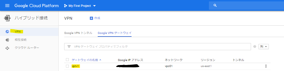
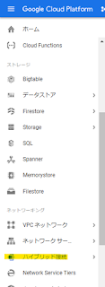 |
| ネットワーキングから「ハイブリッド接続」を選択 |
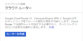 |
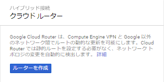
| 「ルーターを作成」をクリック |
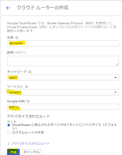 |
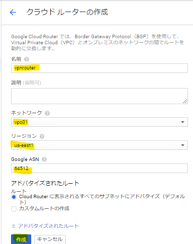
必要事項を記入する。
今回, BGPのAS NoはGCP側は64512とした。 |
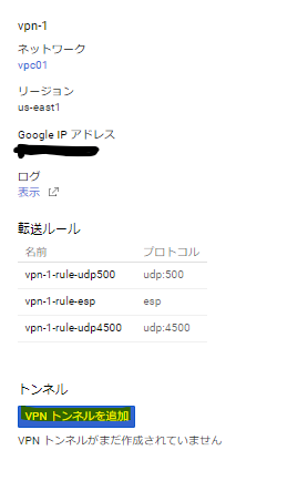
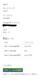 |
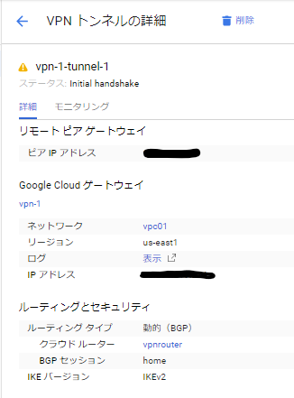
| ルーター作成後, 「VPNトンネルを追加」する。 |
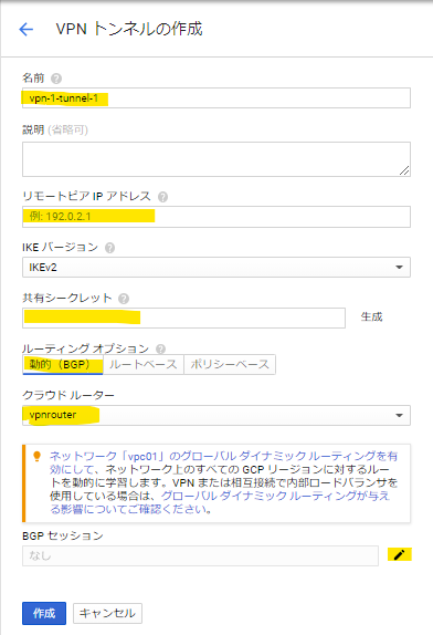
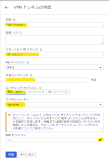 |
| 各項目を記入し, BGPセッションの編集ボタンをクリック。 |
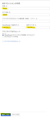 |
| ここでは家側のAS Noを65000とし, トンネル間のセグメント情報を記入する。 |
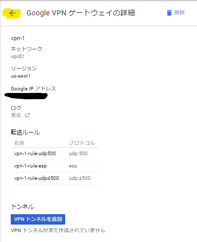
 |
| 設定の結果を確認。 |
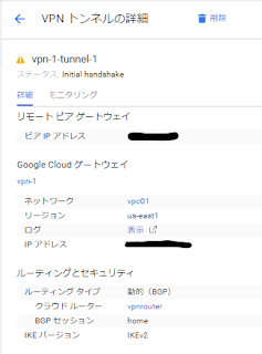 |
| これでGCP側は完了。 |
2. VPN設定(Cisco)
VTIに準じた設定を入れていく。
関連Config抜粋
crypto ikev2 proposal GCP_proposal
 encryption aes-cbc-256 aes-cbc-192 aes-cbc-128
 integrity sha256
 group 16
!
crypto ikev2 policy GCP_policy
 proposal GCP_proposal
!
crypto ikev2 keyring GCP_Key
 peer GCP
  address <GCPのIPアドレス>
  pre-shared-key <共有キー>
 !
!
!
crypto ikev2 profile IKEv2_Profile
 match identity remote address <GCPのIPアドレス> 255.255.255.255
 identity local address <家のGlobal IP>
 authentication remote pre-share
 authentication local pre-share
 keyring local GCP_Key
 lifetime 3600
!
!
crypto ipsec transform-set TS esp-aes 256 esp-sha256-hmac
 mode tunnel
!
crypto ipsec profile GCP_Profile
 set transform-set TS
 set pfs group16
 set ikev2-profile IKEv2_Profile
!
crypto ipsec profile VTI
 set transform-set TS
 set pfs group16
!
interface Tunnel1
 ip address 169.254.1.2 255.255.255.252
 tunnel source Vlan100
 tunnel mode ipsec ipv4
 tunnel destination <GCPのIPアドレス>
 tunnel protection ipsec profile GCP_Profile
!
!
router bgp 65000
 bgp log-neighbor-changes
 network 192.168.1.0
 network 192.168.10.0
 neighbor 169.254.1.1 remote-as 64512
!
通信確認
#ping 10.10.10.10 source 192.168.1.2
Type escape sequence to abort.
Sending 5, 100-byte ICMP Echos to 10.10.10.10, timeout is 2 seconds:
Packet sent with a source address of 192.168.1.2
!!!!!
Success rate is 100 percent (5/5), round-trip min/avg/max = 160/160/160 ms
IPSecステータス
#show crypto session
Crypto session current status

Interface: Tunnel1
Profile: IKEv2_Profile
Session status: UP-ACTIVE
Peer: 35.231.219.234 port 4500
  Session ID: 2209
  IKEv2 SA: local 192.168.1.2/4500 remote 35.231.219.234/4500 Active
  IPSEC FLOW: permit ip 0.0.0.0/0.0.0.0 0.0.0.0/0.0.0.0
        Active SAs: 2, origin: crypto map
無事接続確認完了。